Spur Gear Motor GM24FMN20D
The GM24FMN20 Series is a compact 24 mm-class DC spur gear motor platform designed for small mechanisms that require controlled low-speed output, efficient spur-gear reduction, and a compact linear-drive interface. The supplied GM24FMN20D006-50K reference configuration uses a 1:50 gear ratio and 6 VDC rated voltage, delivering 300 ±10% RPM at no load and 250 ±10% RPM at the rated operating point. The reference rated torque is 100 gf·cm, with a minimum stall torque of 400 gf·cm.
Product Overview
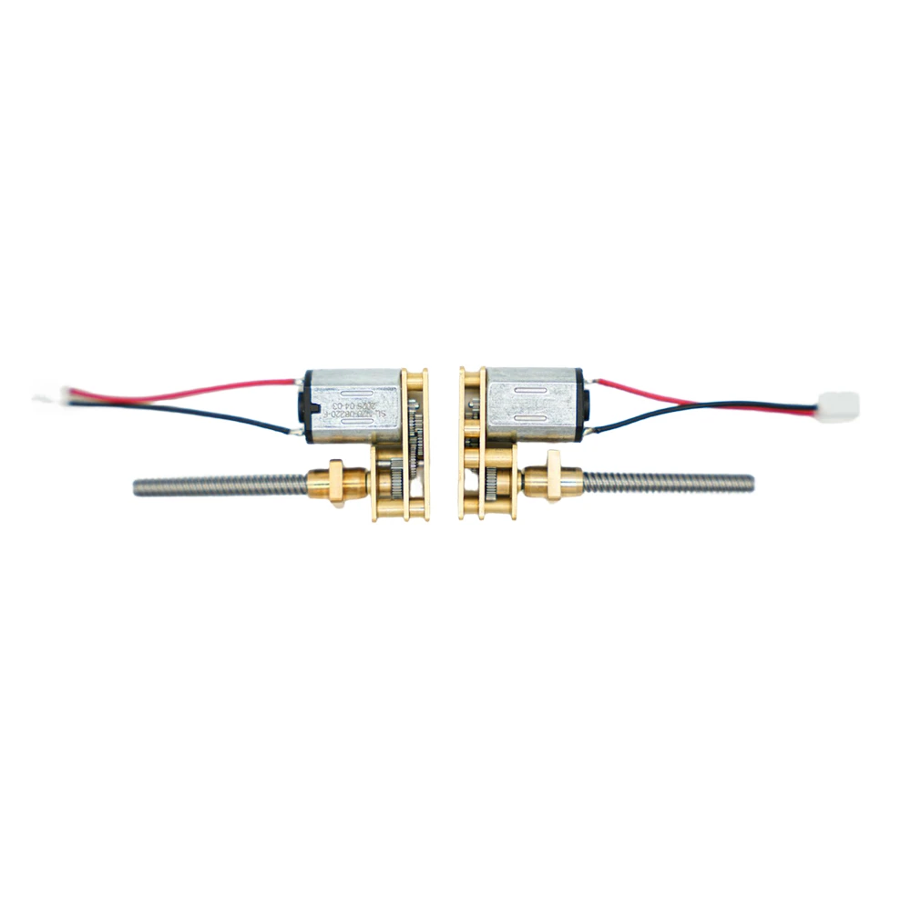
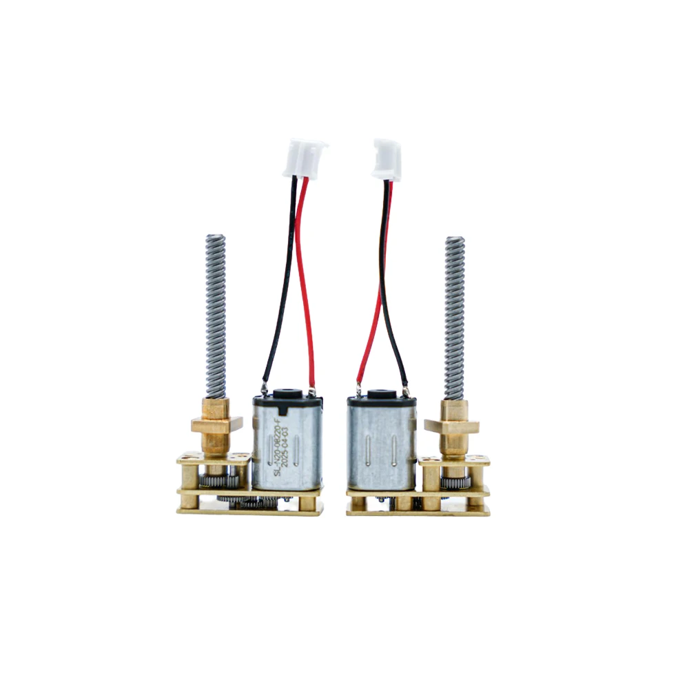
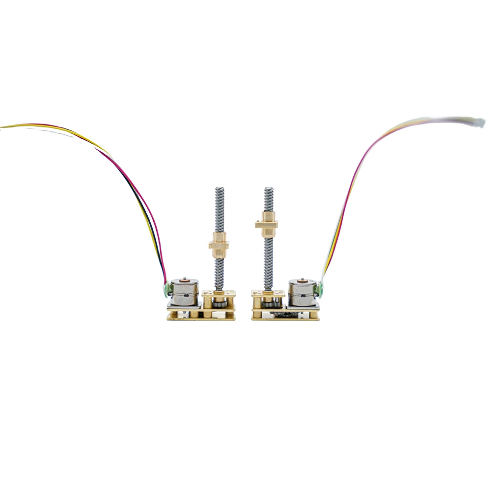
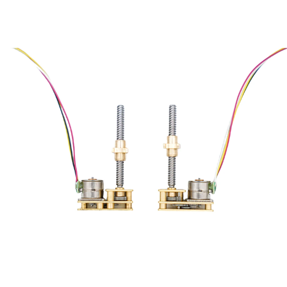
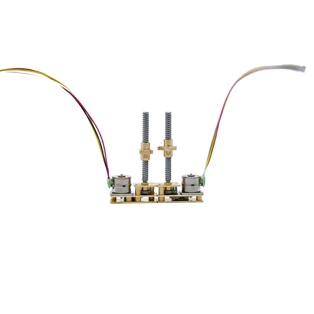
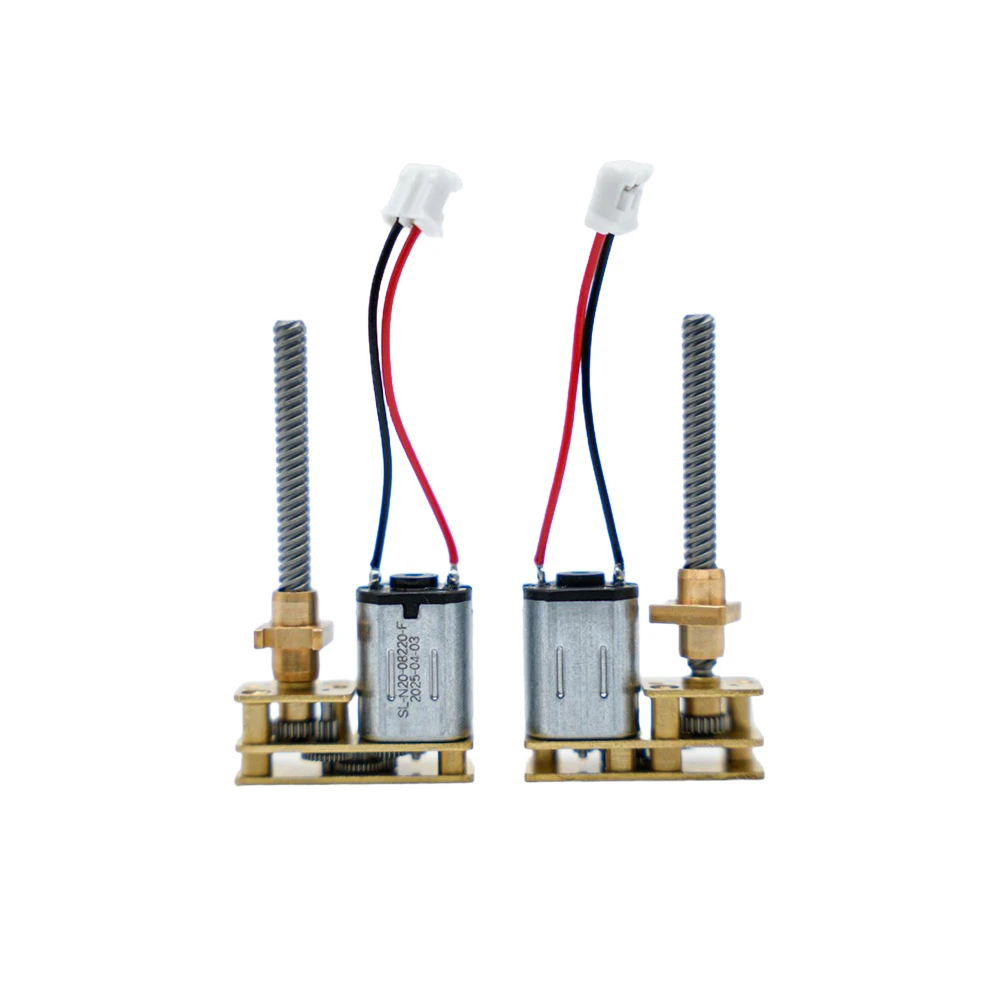
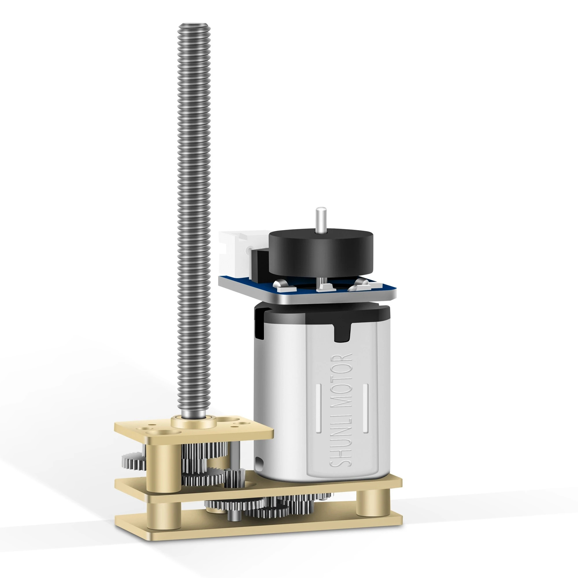
The GM24FMN20 Series is a compact 24 mm-class DC spur gear motor platform designed for small mechanisms that require controlled low-speed output, efficient spur-gear reduction, and a compact linear-drive interface. The supplied GM24FMN20D006-50K reference configuration uses a 1:50 gear ratio and 6 VDC rated voltage, delivering 300 ±10% RPM at no load and 250 ±10% RPM at the rated operating point. The reference rated torque is 100 gf·cm, with a minimum stall torque of 400 gf·cm. Its N20 brushed DC motor, compact 24 mm gearbox, lead-screw interface, and customizable ratio/shaft options make it suitable for miniature linear actuators, smart-home mechanisms, compact automation modules, dispensing systems, locking mechanisms, and other OEM micro-drive applications.
For engineering selection, confirm the required travel speed, axial load, duty cycle, allowable current, lead-screw geometry, installation space, noise target, and jam/stall conditions. The supplied drawing specifies stall operation is not allowed; final performance should therefore be validated in the complete customer mechanism with appropriate current and timeout protection.
Model Information
| Reference Model | Motor | Ratio | Rated Voltage | Product Category |
| GM24FMN20D006-50K | N20 PMDC Motor | 1:50 | 6 VDC | DC Spur Gear Motor / Lead-Screw Drive |
Reference Gearmotor Performance
| Gearmotor Model | Ratio | Rated Voltage (V) | No-Load Speed (RPM) | No-Load Current (mA) | Rated Speed (RPM) | Rated Current (mA) | Rated Torque mN.m / gf.cm | Stall Current (mA) | Stall Torque mN.m / gf.cm |
| GM24FMN20D006-50K | 1:50 | 6 VDC | 300 ±10% | ≤ 50 | 250 ±10% | ≤ 150 | 100 gf·cm (REF) | ≤ 700 | ≥ 400 gf·cm |
Gearbox Technical Data
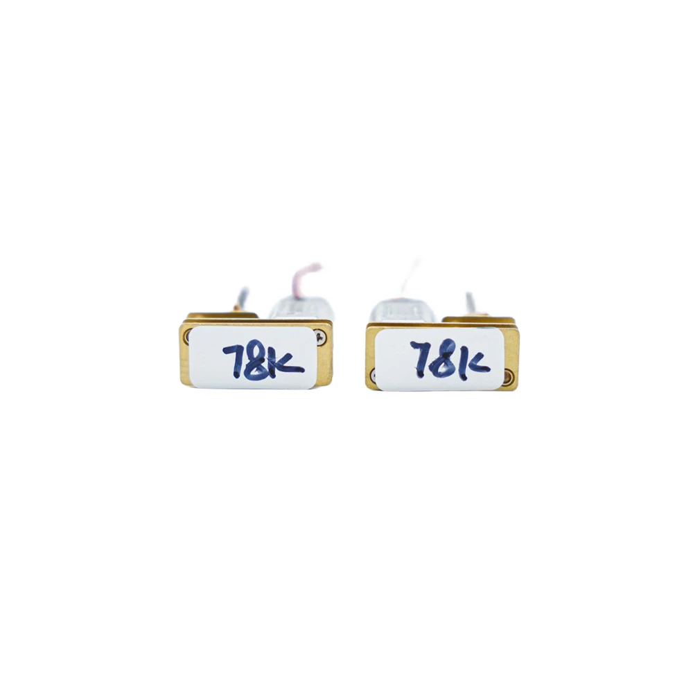
The supplied GM24FMN20 family reference identifies a 24 mm gearbox platform with selectable reduction ratios. The product-family data lists 10 / 50 / 78 / 100 / 150 / 200 / 298 / 500 as available or customizable ratios. The current GM24FMN20D006-50K drawing is a 1:50 configuration; allowable torque and lifetime must be confirmed for the selected ratio, lead-screw load, and operating cycle.
| Item | Reference Data |
| Available Gear Ratios | 10 / 50 / 78 / 100 / 150 / 200 / 298 / 500 |
| Gearbox Width | 24 mm reference |
| Voltage Family Reference | 4.5-12 V customizable; current drawing rated at 6 VDC |
| Output Speed Family Reference | 10-500 RPM customizable; current drawing rated speed 250 ±10% RPM |
| Selection Note | Confirm ratio, lead-screw load, duty cycle, current limit and stall protection for the final configuration. |
PMDC Motor Technical Data
| PMDC Motor Model | Motor Length L (mm) | Rated Voltage (V) | No-Load Speed (RPM) | No-Load Current (mA) | Rated Speed (RPM) | Rated Current (mA) | Rated Torque mN.m / gf.cm | Stall Current (mA) | Stall Torque mN.m / gf.cm |
| N20 | Not separately specified | 6 VDC | 15000 ±10% | ≤ 35 | Not separately specified | Not separately specified | Not separately specified | Not separately specified | Not separately specified |
Dimension Drawing
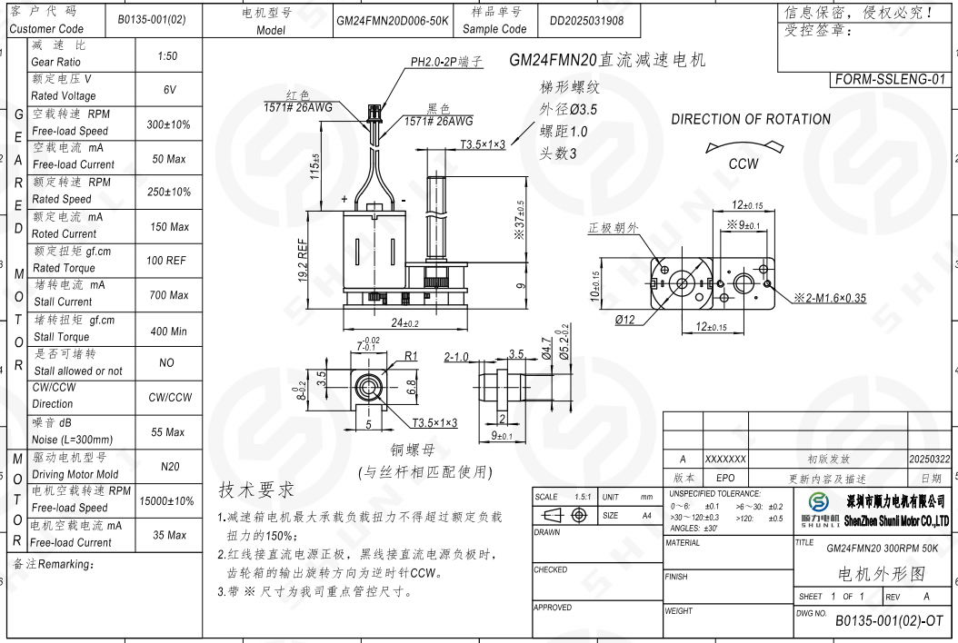
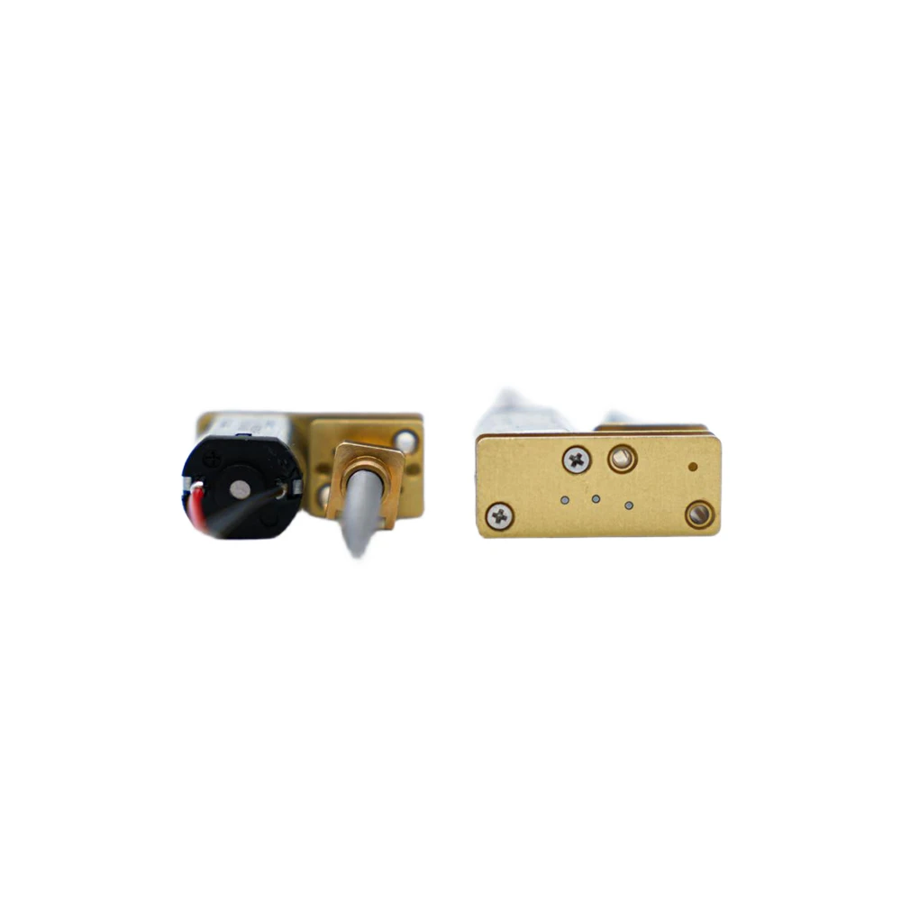
The supplied GM24FMN20D006-50K drawing shows a 24 ±0.2 mm gearbox width, a 1:50 reduction ratio, N20 drive motor, PH2.0-2P connector, and red/black UL1571 26AWG lead wires. The lead-screw interface is marked T3.5×1×3, and the mounting face uses two M1.6×0.35 threaded holes. The drawing provides a CCW rotation reference for the illustrated polarity. Final lead-screw length, nut geometry, travel range, and customer-side mounting should be confirmed against the actual mechanism.
Engineering Value for Product Development
Compact 24 mm spur-gear platform for miniature linear-drive mechanisms
The GM24FMN20 configuration combines an N20 brushed DC motor, compact spur gearbox, and lead-screw output interface for space-constrained mechanisms requiring controlled rotary-to-linear transmission.
1:50 reference ratio with additional ratio customization
The supplied drawing specifies a 1:50 ratio, while the product-family reference lists 10 / 50 / 78 / 100 / 150 / 200 / 298 / 500 as selectable or customizable ratios. Ratio selection should balance target travel speed, load, current, noise, and cycle time.
Rated and stall load must be treated separately
The reference gearmotor data specifies 100 gf·cm rated torque and at least 400 gf·cm stall torque. Because the drawing explicitly states that stall operation is not allowed, jam conditions should be handled by current limiting, timeout control, reverse-release logic, or mechanical protection rather than sustained stall.
Current and noise references support system-level validation
The supplied data specifies ≤50 mA no-load current, ≤150 mA rated current, ≤700 mA stall current, and ≤55 dB noise at L=300 mm. Final current, acoustic behavior, temperature rise, and service life should be validated in the customer mechanism.
Lead-screw interface should be validated with the actual axial load
For linear-drive applications, confirm lead-screw geometry, axial force, nut material, travel length, alignment, lubrication, end-stop behavior, and jam protection together with the selected gear ratio and motor operating point.
Main Applications

Smart Agriculture & Gardening
Electric pruning tools, automatic feeding equipment, small irrigation devices, spraying equipment, quantitative feeding, rotary adjustment and automatic opening/closing mechanisms.
Focus: Evaluate dust/moisture exposure, startup resistance, jam conditions, gear material, lubrication and product-level sealing in the real equipment.
Automotive Electronics
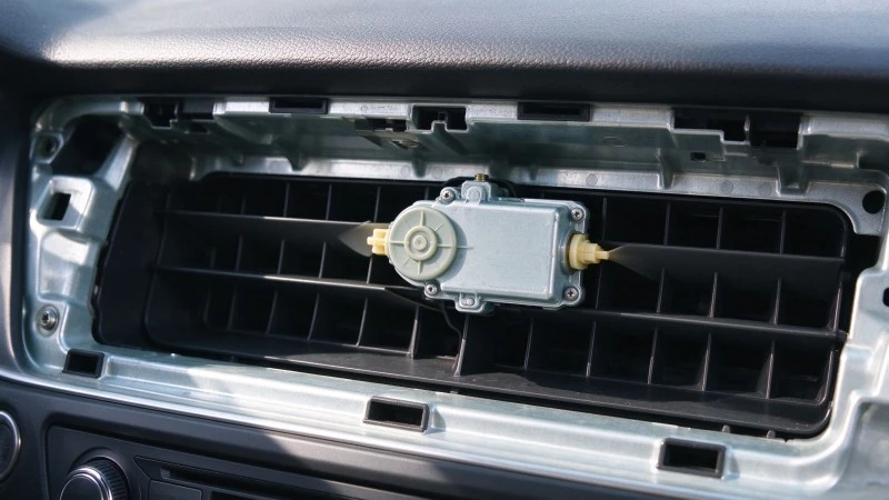
Automotive door locks, charging-port covers, HVAC air flaps, hidden door handles and other small opening/closing mechanisms.
Focus: Validate high/low-temperature start, vibration, stall, noise, duty cycle and batch consistency according to the customer project standard.

Smart Home
Smart door locks, electric curtains, window openers, smart blinds, automatic soap dispensers, smart bins and compact appliance actuators.
Focus: Balance noise, power consumption, startup current, speed, torque, package size and repeated-cycle reliability.
Medical Equipment
Electronic blood pressure monitors, drug-dispensing equipment, sample transport mechanisms, medical valves and compact rotate/push-pull/open-close/quantitative actuators.
Focus: Evaluate noise, vibration, temperature rise, duty cycle, stall protection and batch consistency inside the actual device.
AI Robots
Service-robot grippers, hatches, feeding mechanisms, cleaning modules and light-load joints.
Focus: For frequent start-stop or reversing, verify gear impact, wear, backlash, lubrication, output-shaft loading and cycle life.
Industrial Automation
Small conveyors, feeders, sorting mechanisms, labeling equipment, automatic fixtures and inspection equipment.
Focus: Separate continuous, starting and peak torque requirements; match motor, ratio and stage count to the actual cycle rather than applying one generic safety factor.
Commercial / Office Equipment
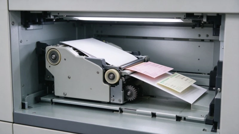
Coffee machines, printers, copiers, smart lockers and ticketing equipment for feeding, dispensing, opening/closing, locking and transmission.
Focus: Evaluate jam/stall peak torque, noise, cycle life and recovery logic while controlling package size and cost.
Custom Drive Applications
Non-standard small transmission mechanisms where standard voltage, speed, ratio, shaft, mounting or motor configuration does not fit.
Focus: Re-match motor, ratio, stage count, output shaft and operating point to the customer mechanism and validation target.
Customization Range
Gear Ratio & Linear Output Matching
Select the reduction ratio together with the lead-screw geometry to match target travel speed, axial force, current, noise, and duty cycle. The supplied family reference lists 10 / 50 / 78 / 100 / 150 / 200 / 298 / 500 ratios as available or customizable.
Motor Configuration
The supplied reference uses an N20 PMDC motor at 6 VDC. The product-family material indicates 4.5-12 V customization; project-specific voltage and operating point should be confirmed through engineering evaluation.
Output Shaft / Lead Screw
Lead-screw dimensions, screw length, nut geometry and output interface can be evaluated for the customer mechanism. The supplied drawing identifies a T3.5×1×3 lead-screw reference.
Performance Matching
Output speed, torque and current should be matched to the actual continuous/start/peak load and duty cycle. A target RPM alone is insufficient for reliable selection.
Gear / Lubrication Optimization
For noise, life, start-stop or environmental requirements, gear material, meshing condition and lubrication can be evaluated as part of the project solution.
Wiring / Interface
Lead wire and terminal/interface requirements can be evaluated from drawings, samples and assembly constraints.
Validation & Mass Production
Sample-stage validation can cover speed, current, torque, noise, temperature rise, stall/jam behavior, cycle life and installation fit; pilot production should confirm process capability and batch consistency.
Information Required for Custom Evaluation
End product and motion task
Working voltage
Target output speed
Continuous, starting and peak torque requirements
Installation space and output-shaft/interface drawing
Single-cycle run time and daily operating cycles
Start-stop / reversing frequency
Expected jam or stall conditions
Ambient temperature, noise target and expected service life
Annual demand and validation/certification requirements
FAQ
Q1. What information is required to select a GM24FMN20 spur gear motor?
Provide working voltage, target travel/output speed, axial load or equivalent torque, lead-screw geometry, installation space, run time per cycle, daily cycle count, jam/stall conditions, noise target, life target and annual demand. If parameters are incomplete, a mechanism drawing or existing sample can be used for initial matching.
Q2. How should engineers choose the gear ratio for a lead-screw mechanism?
Start from the target linear travel speed and required axial force, then match the lead-screw geometry, gear ratio, motor speed, current and duty cycle. A higher ratio is not automatically better because it can reduce travel speed and change efficiency, noise and cycle time.
Q3. Can the GM24FMN20 be used when the mechanism may jam?
It can be evaluated, but the supplied drawing states that stall operation is not allowed. Normal operating load and jam/stall load must be treated separately, and the system should use appropriate current limiting, timeout, reverse-release or mechanical protection when blockage is possible.
Q4. How can noise be reduced?
Noise should be optimized at system level through motor operating speed, ratio and stage selection, gear meshing, lubrication, assembly consistency, mounting stiffness and enclosure resonance. Final acceptance should be performed in the customer's actual product rather than by motor no-load noise alone.
Q5. What can be customized for a GM24FMN20 project?
The supplied product-family data supports gearbox ratio, voltage, speed and shaft/output customization. For lead-screw projects, screw length, nut/interface geometry, wiring and installation details should be confirmed through engineering evaluation.
Q6. What should purchasing teams provide for quotation and mass-production evaluation?
Provide the target model or performance requirement, drawing/sample, estimated annual demand, expected validation items and critical quality/delivery requirements. For customized projects, the sample scope and volume-production acceptance criteria should be confirmed after the technical solution is frozen.
Parameter Integrity Note
All numerical values for the GM24FMN20D006-50K reference configuration are taken from the supplied engineering drawing and product-family parameter image. Where the two sources differ in scope, the formal engineering drawing is treated as the primary reference for this specific sample. The 30 kgf·cm maximum torque shown in the family marketing table is not used as the rated torque of this 1:50 sample; the specific drawing values of 100 gf·cm rated torque reference and ≥400 gf·cm stall torque are used instead. Final production specifications should be confirmed on the approved drawing/specification.
Product Categories
Enable Customized Solutions to Be Implemented Faster
Whether you're in the product concept, prototype development, or mass production phase, Shunli Motors can help you find the right micro geared motor drive solution based on your specific application needs.
Submit your product requirements now and get selection advice from our engineers.
Related Products
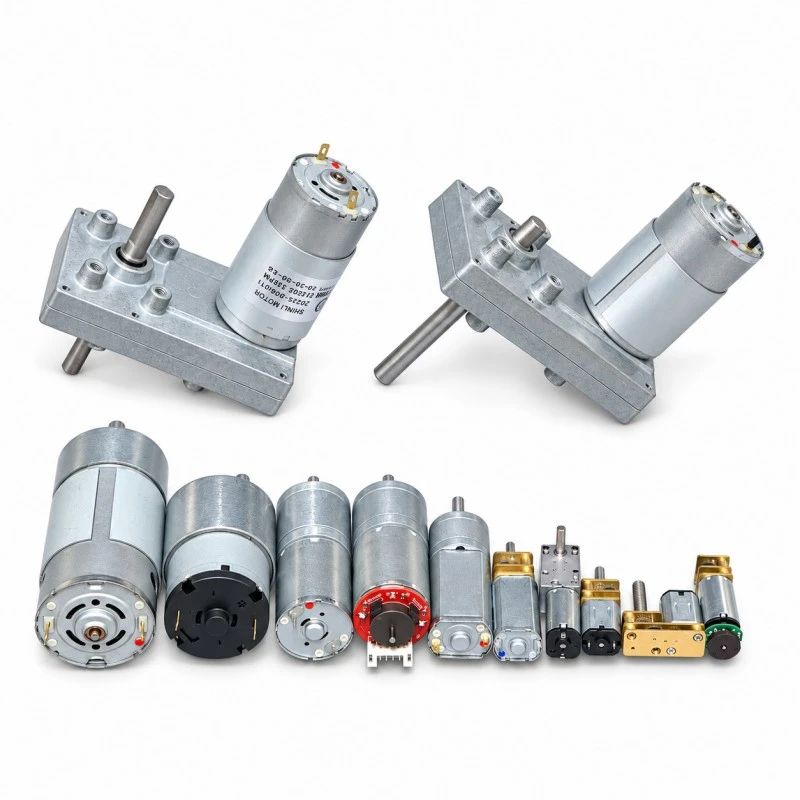
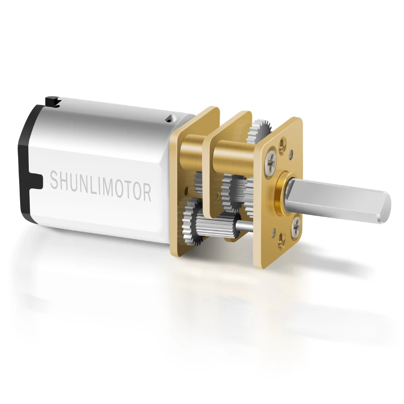
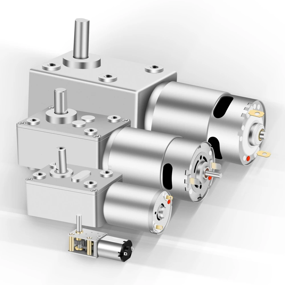
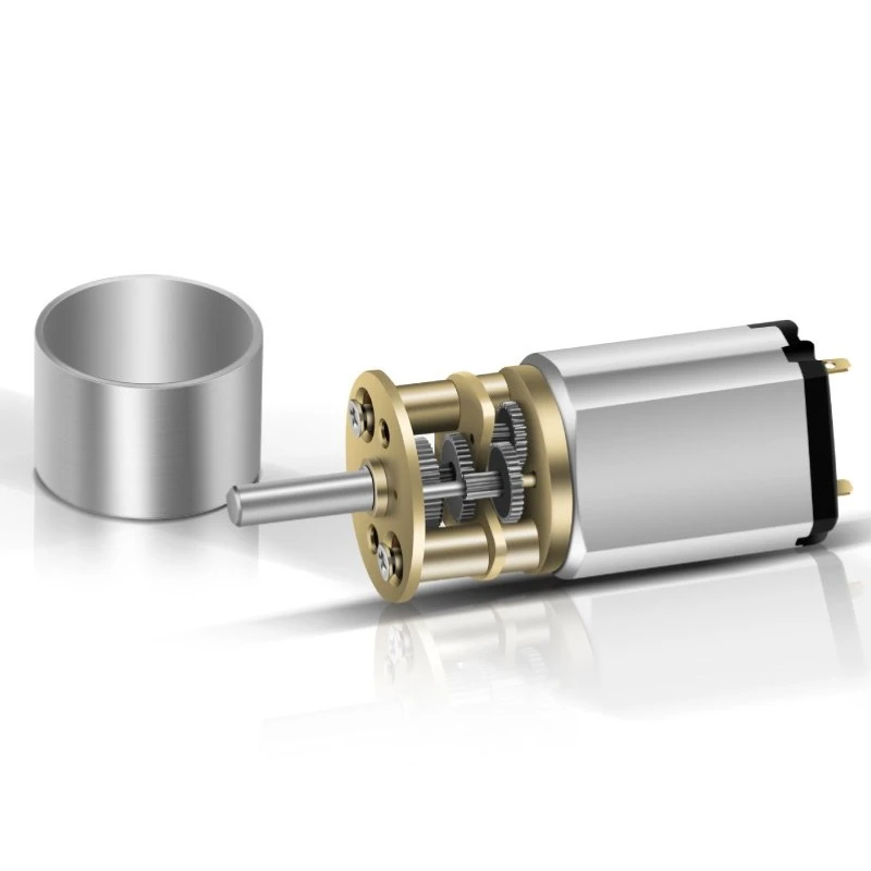
The Spur Gear Motor combines a DC motor with a multi-stage spur gearbox to provide a mature, efficient, and cost-effective drive solution for compact transmission mechanisms. Its simple gear structure supports flexible ratio, shaft, and mounting customization, making it suitable for smart home devices, commercial equipment, automotive actuators, smart landscaping systems, and industrial automation. It is a practical choice for projects that need a balance of output speed, torque, reliability, manufacturability, and cost.
The GM12 Series is a compact 12 mm-class DC spur gear motor platform developed for miniature mechanisms that require efficient speed reduction, controlled output, and cost-effective integration in limited space.
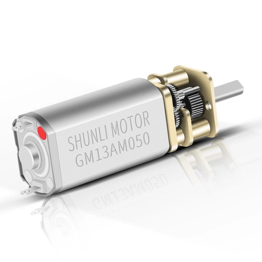
The GM13AM Series is a compact 13 mm-class DC spur gear motor designed for miniature mechanisms that require efficient speed reduction, stable low-speed output, and cost-effective transmission in a limited installation space.
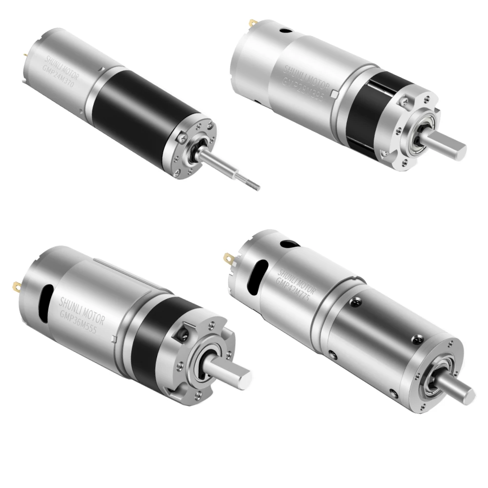
The Planetary Gear Motor uses a compact coaxial planetary gearbox to deliver higher torque density and stable transmission within limited installation space. Multiple planet gears share the load, making the structure suitable for applications that require compact size, reliable load handling, and frequent start-stop or reversing motion. It is widely used in robotics, medical equipment, industrial automation, automotive actuators, precision mechanisms, and other compact motion systems. Final selection should consider output speed, continuous and peak torque, duty cycle, backlash, current, and installation requirements.
The DC Worm Gear Motor combines a DC motor with a worm gearbox to provide right-angle transmission, high reduction ratios, low-speed output, and strong load-driving capability in a compact structure. Its 90° output arrangement is well suited to valves, lifting and adjustment mechanisms, doors and windows, vending equipment, and other actuators where space layout or load-holding performance is important. Depending on the gear geometry and operating conditions, some worm gear designs may provide holding or self-locking characteristics, which should be verified for the actual application.
The GM16 Series is a compact 16 mm-class DC spur gear motor platform designed for miniature transmission systems that require efficient speed reduction, controlled low-speed output, cost-effective construction, and repeatable mass production.
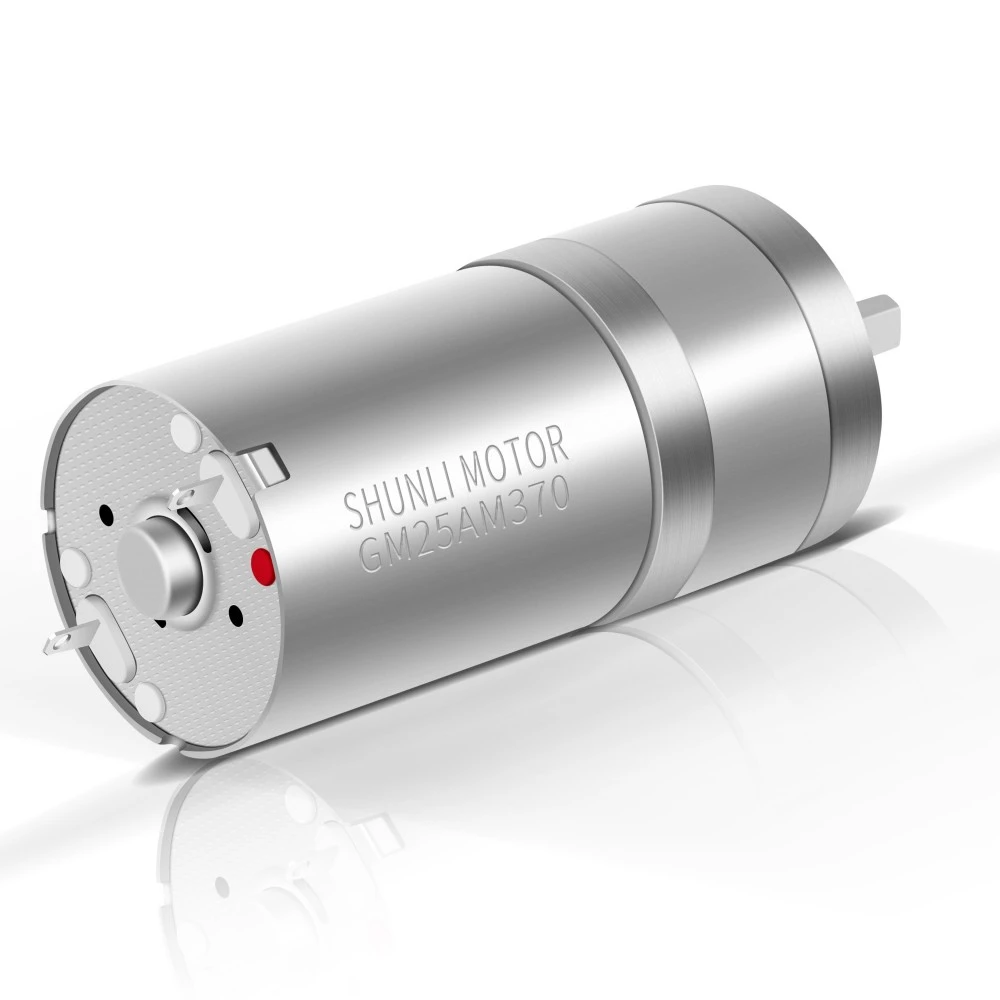
The GM25AM310/370 is a 25 mm-class DC spur gear motor platform combining a compact multi-stage gearbox with PMDC 310 or 370 motors. The supplied technical data covers gearbox options from 3 to 8 stages, multiple reduction ratios, and two reference gearmotor configurations: GM25AM310-217K at 3 VDC and GM25AM370-99K at 12 VDC.
The GM24 Series is a compact 24 mm-class DC spur gear motor platform developed for small transmission mechanisms that require efficient speed reduction, stable output, and cost-effective mass production.
Navigation
Navigation
Product Categories
Product Categories
Contact Us
Get in Touch
Get in Touch
Request a Quote



 Youtube
 Tiktok
 Linkedin
 Instagram
 Facebook
 WhatsApp
 WeChat