Brushed Worm Gear Motor: How It Works and Where to Use It
Brushed Worm Gear Motor: How It Works and Where to Use It
Nov. 18, 2026
A brushed worm gear motor combines a brushed DC motor with a worm reduction gearbox to deliver controlled, low-speed rotation and increased output torque. This guide explains how it works, how to choose one for a real application, and what to check before installation. Shunli Motor helps buyers compare motor and gearbox requirements so they can avoid mismatched voltage, speed, torque, and mounting dimensions.
People researching a brushed worm gear motor usually want more than a definition. They need to know whether the motor can move their load, fit their equipment, run for the required duty cycle, and remain within their budget. A practical buying decision connects the motor's electrical characteristics with the gearbox output and the application's mechanical demands.
A motor's advertised torque or speed may refer to a particular test condition. Ask for the continuous rating, permitted peak load and duration, output speed under load, current draw, and operating limits. Confirm that the supplier's figures apply to the exact voltage and gearbox ratio you plan to use.
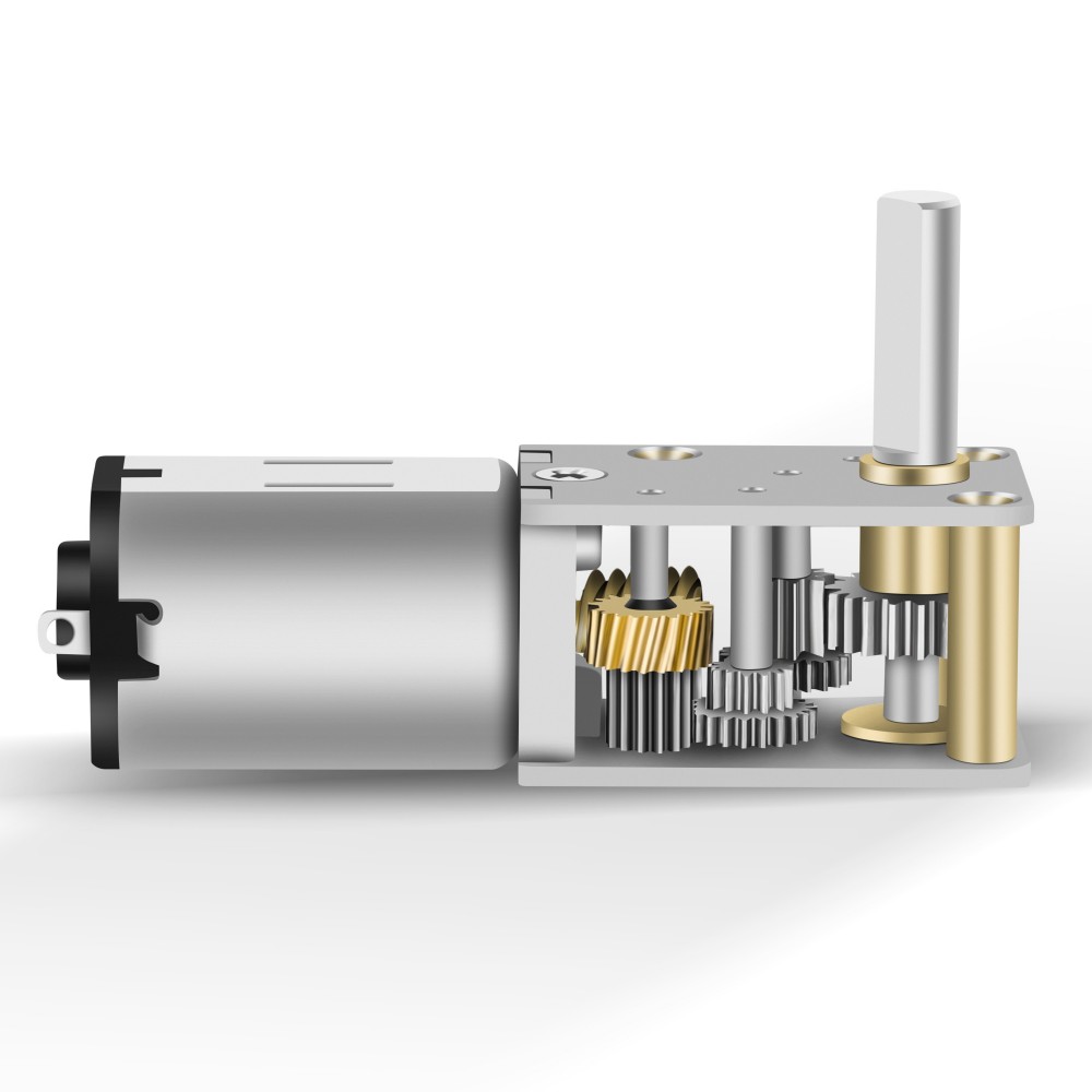
The brushed DC motor converts electrical energy into rotation. Inside the motor, brushes transfer current to the rotating commutator, creating the magnetic forces that turn the armature. The motor shaft drives a worm, which meshes with a worm wheel inside the gearbox. The wheel turns the output shaft, usually on an axis at a right angle to the worm shaft.
A worm gearbox can provide substantial reduction in a compact arrangement and can make it easier to package a drive where the input and output shafts need to be perpendicular. Some worm gear designs resist backdriving, but self-locking is not guaranteed. It depends on factors such as the gear design, lead angle, lubrication, wear, vibration, and load. Use a brake or other load-holding method when a falling or moving load could create a hazard.
Increasing the reduction ratio generally lowers output speed and raises available output torque, but gearbox losses reduce the torque available at the shaft. Worm gears can also generate heat during operation. Do not calculate a final design using the ratio alone; use the supplier's rated output torque, efficiency, thermal limits, and duty-cycle guidance.
Start with the load rather than selecting a motor by size or price. Establish the required output speed, the force or torque needed to move the load, and any extra demand caused by starting, friction, incline, or impact. A design that only works at no load is not adequately sized.
Use these calculations for an initial estimate, then verify the result against the motor manufacturer's performance data. For a rotating load, output torque is the required load torque plus allowance for friction and starting demand. For a translating load, first estimate the force needed to move it, then convert that force to shaft torque using the effective drive radius.
Ask the supplier to identify whether speed and torque figures are nominal, continuous, or peak values. Request a dimensional drawing, wiring information, allowable shaft loads, operating temperature range, gearbox lubrication details, and sample or production testing options. Provide the intended duty cycle and load profile so the recommendation is based on actual use.
A brushed worm gear motor can suit equipment that needs a compact, geared drive with relatively low output speed and useful torque. Typical applications include:
A brushed motor can be a straightforward option where simple DC control and cost are priorities. However, brushes wear over time and may require maintenance. A brushless motor may be preferable for long service life, frequent operation, or reduced brush maintenance. A different gearbox or a brake-equipped drive may be needed for high efficiency, precise positioning, frequent reversing, or loads that must stay in place when power is removed.
Application suitability depends on the motor, gearbox, controller, power source, mounting structure, and driven load working together. Confirm that the output shaft and mounting can handle radial and axial loads. Do not assume the gearbox can support the load directly unless its allowable shaft-load ratings confirm it.
Prepare the equipment and application data before installation. The exact requirements depend on the motor and machine, but this checklist is a useful starting point.
Record the load, target output speed, required torque, supply voltage, duty cycle, starting frequency, environment, and available installation space. Note whether the motor must reverse, stop at a specific position, or hold a load when power is removed. These requirements form the basis for model selection.
Compare the motor's rated voltage, continuous current, output speed, continuous torque, peak limits, and duty-cycle restrictions with your application. Check the gearbox's allowable output torque and shaft loads. If a load may backdrive the gearbox, specify a brake or another approved holding solution rather than relying on the gearbox alone.
Use the dimensional drawing to verify the gearbox shape, mounting holes, shaft diameter, shaft length, and clearance around the motor. Confirm that the driven component aligns with the output shaft. Avoid forcing a coupling onto the shaft or using the motor housing to compensate for poor alignment.
Fasten the motor to a rigid support using the recommended hardware. Keep the output shaft aligned with the driven mechanism and make sure the load is supported independently where required. Follow the manufacturer's instructions for fastener size and tightening. Excessive tightening or a flexible mounting surface can distort the assembly or cause vibration.
Disconnect power before making connections. Follow the motor and controller wiring diagrams, verify polarity, and use wire and connectors rated for the current. Add appropriate overcurrent protection. If the controller changes direction by reversing motor polarity, confirm that it is designed for the motor's startup and stall current. Secure the wiring so it cannot rub against moving parts or pull on the terminals.
With the mechanism clear and secured, apply power briefly and check the direction of rotation, unusual noise, vibration, and current draw. Disconnect power before changing wiring. If rotation is opposite to the required direction, use the approved controller or polarity-reversal method. Do not repeatedly stall the motor to test its strength.
Connect the load and run the system at the expected operating conditions. Observe startup, speed, current, temperature, noise, and stopping behavior. Start with short test runs, then extend the test only if the unit stays within its ratings. Check that the motor and gearbox do not become excessively hot and that the mounting remains secure.
Document the supply voltage, operating current, load, run time, temperature observations, and controller settings. Use those results to confirm the selected motor is suitable. Follow the manufacturer's guidance for inspection, cleaning, brush service, gearbox maintenance, and replacement intervals.
Peak torque may only be available briefly and may create high current and heat. For recurring or continuous work, size the system using continuous output ratings and confirm the permitted peak duration for startup or short events.
A worm gearbox may resist backdriving in some conditions, but it is not a dependable safety brake by default. Test the complete system and use a rated brake or other load-holding device where uncontrolled movement could cause damage or injury.
Brushed DC motors can draw much more current during startup or when stalled than while running freely. An undersized supply, controller, wire, or connector can overheat or fail. Check current ratings and provide suitable protection.
No-load speed does not show how the motor behaves with the actual mechanism attached. Confirm loaded speed and torque using performance data or a representative test.
Excess radial or axial force can damage gearbox bearings and shorten service life. Align the driven assembly, use suitable supports, and compare the load with the manufacturer's shaft-load limits.
Frequent starts, long run times, heavy loads, and poor ventilation can raise temperature and accelerate wear. State the full operating pattern when selecting a motor and plan inspection according to the manufacturer's recommendations.
Similar-looking models can differ in voltage, ratio, shaft size, mounting pattern, wiring, or rotation direction. Check the exact model number and drawing before approving a sample or placing a production order.
Set an inspection frequency that matches the duty cycle and environment. With power isolated, check mounting fasteners, wiring, connectors, shaft alignment, and signs of damage. Follow the supplier's instructions for cleaning, brush inspection, and gearbox lubrication; do not add lubricant unless the gearbox design calls for it.
Before committing to production, provide the load profile, supply voltage, required speed, duty cycle, dimensions, environment, and control method. Ask the supplier to confirm the model, output ratings, fit, and any operating limitations. Shunli Motor can help buyers review these requirements and request the drawings and performance information needed for a more informed decision.
Many brushed DC motors can reverse direction when motor polarity is reversed, but the controller and application must support reversing. Check whether the gearbox and driven equipment allow frequent or loaded reversals.
A higher ratio generally reduces output speed and can increase available output torque, but gearbox efficiency, motor limits, heat, and the rated gearbox torque matter. Confirm the usable output rating rather than relying on ratio alone.
That depends on the specific motor's continuous rating, cooling, load, ambient temperature, and duty cycle. Check the datasheet and validate performance under the actual operating conditions.
Provide the required voltage, output speed, load or torque, duty cycle, starting frequency, dimensions, shaft and mounting requirements, control method, and operating environment. Include drawings or photos of the installation space when possible.
With the load, electrical supply, duty cycle, and mechanical fit verified before purchase, a brushed worm gear motor can be a practical drive for compact, low-speed applications.
Product Categories
Enable Customized Solutions to Be Implemented Faster
Whether you're in the product concept, prototype development, or mass production phase, Shunli Motors can help you find the right micro geared motor drive solution based on your specific application needs.
Submit your product requirements now and get selection advice from our engineers.
Related Products
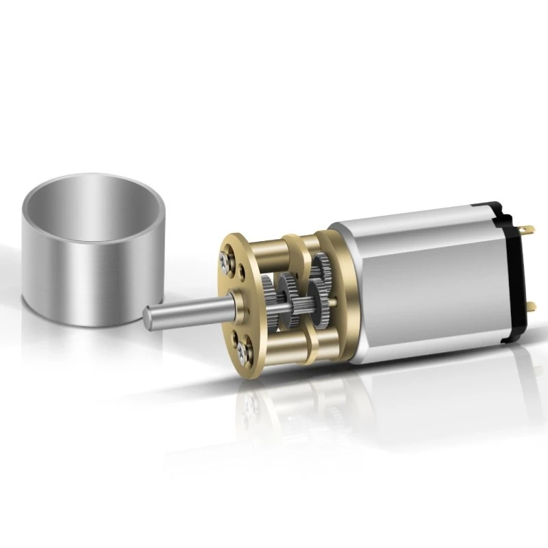
The Spur Gear Motor combines a DC motor with a multi-stage spur gearbox to provide a mature, efficient, and cost-effective drive solution for compact transmission mechanisms. Its simple gear structure supports flexible ratio, shaft, and mounting customization, making it suitable for smart home devices, commercial equipment, automotive actuators, smart landscaping systems, and industrial automation. It is a practical choice for projects that need a balance of output speed, torque, reliability, manufacturability, and cost.
The GM12 Series is a compact 12 mm-class DC spur gear motor platform developed for miniature mechanisms that require efficient speed reduction, controlled output, and cost-effective integration in limited space.
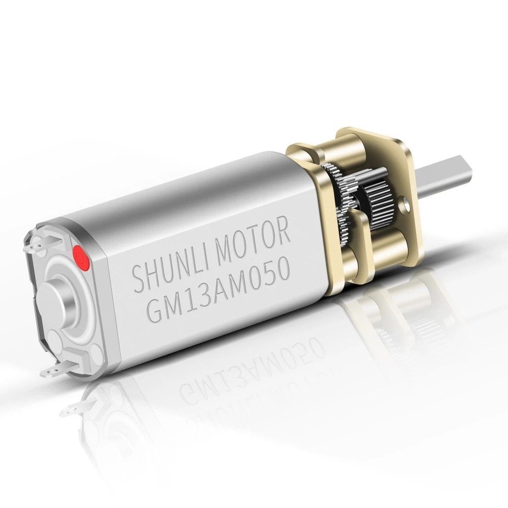
The GM13AM Series is a compact 13 mm-class DC spur gear motor designed for miniature mechanisms that require efficient speed reduction, stable low-speed output, and cost-effective transmission in a limited installation space.
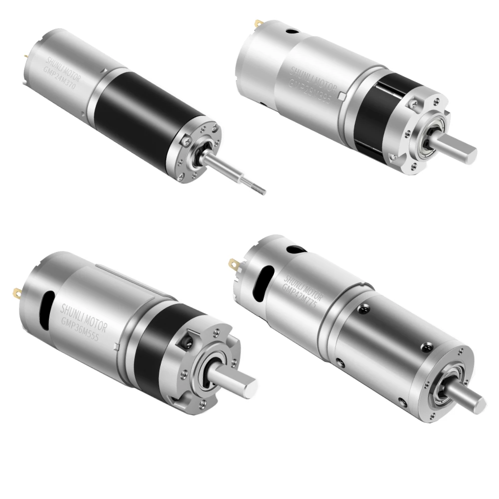
The Planetary Gear Motor uses a compact coaxial planetary gearbox to deliver higher torque density and stable transmission within limited installation space. Multiple planet gears share the load, making the structure suitable for applications that require compact size, reliable load handling, and frequent start-stop or reversing motion. It is widely used in robotics, medical equipment, industrial automation, automotive actuators, precision mechanisms, and other compact motion systems. Final selection should consider output speed, continuous and peak torque, duty cycle, backlash, current, and installation requirements.
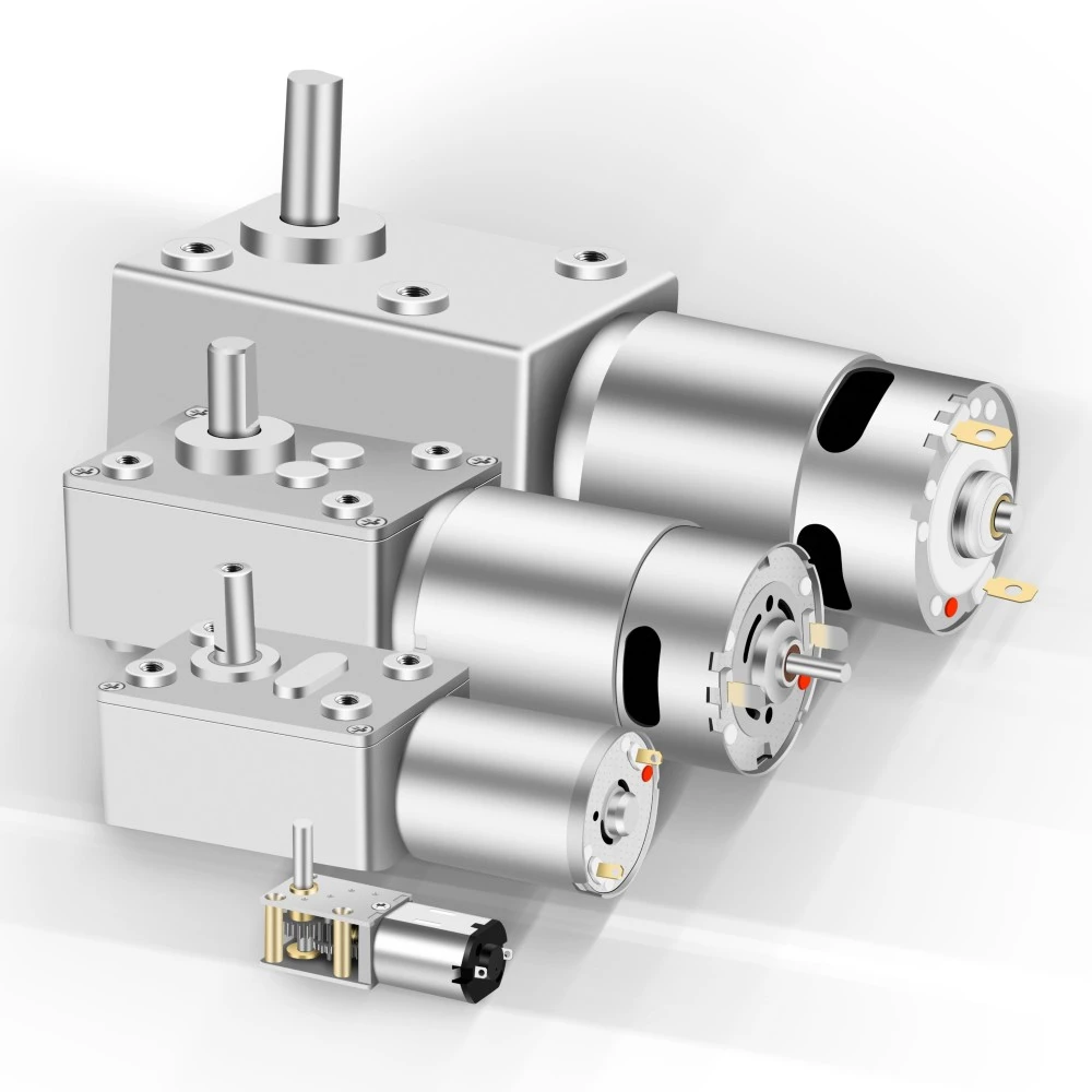
The DC Worm Gear Motor combines a DC motor with a worm gearbox to provide right-angle transmission, high reduction ratios, low-speed output, and strong load-driving capability in a compact structure. Its 90° output arrangement is well suited to valves, lifting and adjustment mechanisms, doors and windows, vending equipment, and other actuators where space layout or load-holding performance is important. Depending on the gear geometry and operating conditions, some worm gear designs may provide holding or self-locking characteristics, which should be verified for the actual application.
The GM16 Series is a compact 16 mm-class DC spur gear motor platform designed for miniature transmission systems that require efficient speed reduction, controlled low-speed output, cost-effective construction, and repeatable mass production.
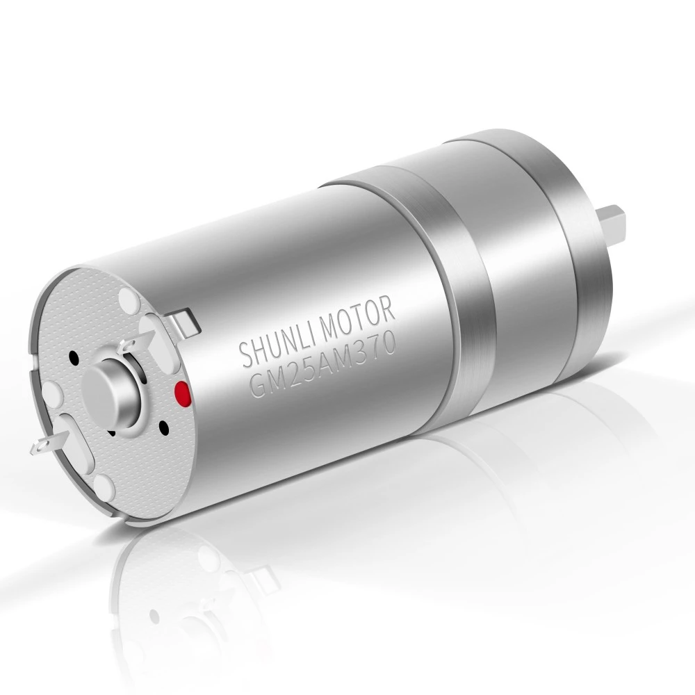
The GM25AM310/370 is a 25 mm-class DC spur gear motor platform combining a compact multi-stage gearbox with PMDC 310 or 370 motors. The supplied technical data covers gearbox options from 3 to 8 stages, multiple reduction ratios, and two reference gearmotor configurations: GM25AM310-217K at 3 VDC and GM25AM370-99K at 12 VDC.
The GM24 Series is a compact 24 mm-class DC spur gear motor platform developed for small transmission mechanisms that require efficient speed reduction, stable output, and cost-effective mass production.
Navigation
Navigation
Product Categories
Product Categories
Contact Us
Get in Touch
Get in Touch
Request a Quote


 Youtube
 Tiktok
 Linkedin
 Instagram
 Facebook
 WhatsApp
 WeChat