DC Worm Gear Motor GM49EM385
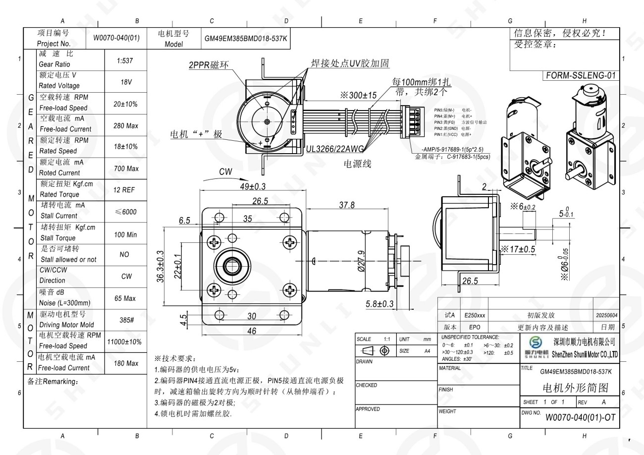
The GM49EM385 DC Worm Gear Motor is an 18 V right-angle high-torque gearmotor designed for compact actuator systems that require large reduction, low output speed, and strong load-driving capability. The supplied GM49EM385BMD018-537K configuration uses a 1:537 reduction ratio and a 385 PMDC motor, providing 20 ±10% RPM no-load speed, 18 ±10% RPM rated speed, a 12 kgf·cm rated-torque reference, and at least 100 kgf·cm stall torque. A 2 PPR magnetic-ring feedback structure is specified in the drawing, enabling basic motion feedback for industrial actuators, robotics, valves, smart equipment, and other OEM mechanisms.
Product Overview
The GM49EM385 DC Worm Gear Motor is an 18 V right-angle high-torque gearmotor designed for compact actuator systems that require large reduction, low output speed, and strong load-driving capability. The supplied GM49EM385BMD018-537K configuration uses a 1:537 reduction ratio and a 385 PMDC motor, providing 20 ±10% RPM no-load speed, 18 ±10% RPM rated speed, a 12 kgf·cm rated-torque reference, and at least 100 kgf·cm stall torque. A 2 PPR magnetic-ring feedback structure is specified in the drawing, enabling basic motion feedback for industrial actuators, robotics, valves, smart equipment, and other OEM mechanisms. As a compact DC worm gear motor with high reduction and right-angle transmission, the GM49EM385 platform is suited to projects where torque density, controlled motion, and integration flexibility are more important than high transmission efficiency. Final selection should be validated against the real duty cycle, reverse load, temperature rise, stall protection, and service-life requirements.
Model Information
| Model | Motor Platform | Rated Voltage | Product Category |
| GM49EM385BMD018-537K | 385# PMDC Motor | 18 VDC | DC Worm Gear Motor |
Main Parameters
Gearmotor Technical Data
| Gearmotor Model | Rated Voltage | No-Load Speed (RPM) |
No-Load Current (mA) |
Rated Speed (RPM) |
Rated Current (mA) |
Rated Torque* | Stall Current* (mA) |
Stall Torque* |
| GM49EM385BMD018-537K | 18 VDC | 20 ±10% | ≤280 | 18 ±10% | ≤700 | 12 kgf·cm REF | ≤6000 | ≥100 kgf·cm |
PMDC Motor Reference Data
| PMDC Motor | System Voltage Reference | No-Load Speed | No-Load Current |
| 385# | 18 VDC | 11000 ±10% RPM | ≤180 mA |
Dimension Drawing
Engineering Value
Right-angle output architecture: The worm gearbox redirects motion by 90 degrees, supporting compact actuator packaging and alternative power-routing paths inside constrained equipment.
Low-speed torque matching: The supplied 1:537 configuration provides 20 ±10% RPM no-load speed and 18 ±10% RPM rated speed, with a 12 kgf·cm rated-torque reference and at least 100 kgf·cm stall torque.
Load-holding advantage: Worm gear transmission can provide useful resistance to reverse driving in suitable configurations. It must not be treated as a certified safety lock without validating reverse-holding torque under the actual ratio, load, vibration, lubrication, wear, and temperature conditions.
Application-specific interface: The drawing provides the gearbox envelope, output interface, mounting references, 220 ±10 mm lead length, PH2.0-2P connector, and red-positive / black-negative wiring for mechanical and electrical integration.
Reliability-focused validation: The source specifies stall operation is not allowed and noise ≤55 dB at 300 mm. For production programs, verify starting current, temperature rise, noise, reversing, overload/stall protection, long-term restart, and target life in the complete mechanism.
Main Applications
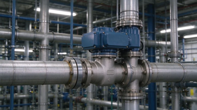
Industrial Automation
Industrial valves, dampers, gates, low-speed rotary platforms, adjustment mechanisms, and compact actuators requiring right-angle transmission.
Focus: Match starting torque, continuous torque, duty cycle, temperature rise, lubrication, and emergency manual-release requirements. Continuous high-load operation must be validated thermally.
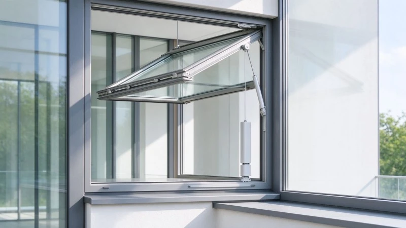
Smart Home & Appliances
Electric doors/windows, smart blinds, smart valves, furniture adjustment, kitchen/bathroom appliances, pet equipment, and automatic opening/closing or lifting mechanisms.
Focus: Balance low noise, current consumption, motion smoothness, and holding performance. Validate frequent start/stop, reversing, long standstill, abnormal stall, and restart in the customer’s actual mechanism.

Commercial & Office Equipment
Electric lifting mechanisms, vending-machine gates, smart cabinet locking/actuation, display lifting, automatic flaps, and other compact opening/closing mechanisms.
Focus: For unattended equipment, validate long-term standstill restart, humidity, lubrication aging, jam recovery, abnormal power interruption, and reverse-holding requirements.

Medical Auxiliary Equipment
Nursing-bed, medical-chair, lifting, positioning, and adjustment mechanisms where low-speed torque or right-angle transmission is needed.
Focus: Any function related to patient safety requires system-level risk control. Reverse holding must be tested, and independent mechanical locking, limit, brake, or protection mechanisms may be required.
Smart Agriculture & Gardening
Ventilation/adjustment mechanisms, irrigation-related actuators, greenhouse opening/closing systems, feeding mechanisms, and equipment height or angle adjustment.
Focus: Evaluate moisture, dust, corrosion, temperature change, vibration, shock, long standstill, abnormal jam, and shaft/interface protection at the complete-product level.
AI & Service Robotics
Low-speed lifting, rotary stages, compact joints, and mechanisms that benefit from right-angle packaging and position holding.
Focus: Worm gearing has sliding friction, so battery-powered systems should calculate energy consumption and temperature rise from the real motion cycle. It may not be the best choice for high-speed or high-efficiency axes.
Automotive Electronics
Window, sunroof, seat, and other actuator concepts requiring right-angle transmission and load holding, subject to automotive-grade validation.
Focus: Anti-pinch or safety functions cannot be achieved by the gearmotor alone. Current sensing, position feedback, control logic, mechanical protection, temperature testing, vibration testing, and life validation are system responsibilities.
Customization Range
Electrical Configuration
Rated voltage, motor platform, winding configuration, rotation direction, lead wire, terminal, and connection requirements.
Performance Matching
Target output speed, reduction ratio, continuous/starting/peak torque, current limit, duty cycle, and operating pattern.
Mechanical Interface
Output direction, shaft shape and length, mounting holes/interface, bracket, bearing/sleeve selection, and gear material.
Feedback & Functional Options
Encoder, Hall/position feedback, limit switch, or related functional modules can be evaluated according to the control architecture.
Noise, Thermal & Reliability Optimization
Gear meshing, lubrication, transmission clearance, temperature rise, stall/overload, reversing, long standstill restart, and target service life can be optimized and validated for the complete product.
Holding & Emergency Requirements
Reverse-holding behavior and manual-release requirements can be evaluated. Safety locking should be handled with appropriate system-level mechanical and control protection.
Information Required for Custom Evaluation
End product and motion task
Working voltage and power-supply limits
Target output speed
Continuous, starting, and peak torque requirements
Installation space and output-shaft/interface drawing
Run time per cycle, daily operating cycles, and reversing frequency
Ambient temperature, humidity/dust conditions, vibration/shock conditions
Noise target, expected service life, and allowable temperature rise
Whether reverse holding, manual release, encoder, Hall feedback, or limit control is required
Annual demand and certification / compliance requirements
If complete parameters are not yet available, an existing motor sample, prototype, mechanism drawing, or load description can be used for an initial engineering evaluation.
FAQ
Q1: What types of projects are best suited to the GM49EM385 DC Worm Gear Motor?
It is best suited to low-speed actuator mechanisms that benefit from right-angle transmission, torque multiplication, compact packaging, and some degree of resistance to reverse driving. Typical examples include valves, gates, opening/closing mechanisms, lifting/adjustment devices, and low-speed rotary mechanisms.
Q2: Can the GM49EM385 be used as a self-locking or safety-locking drive?
Worm gearing can provide useful reverse-holding behavior in suitable configurations, but self-locking is not guaranteed for every reduction ratio, load, lubrication condition, wear state, vibration level, or temperature. For safety-critical holding, validate reverse torque and use independent mechanical or control protection where required.
Q3: How should torque and speed be selected?
Do not select only from no-load speed. Provide target speed plus continuous, starting, and peak torque, along with the transmission mechanism, installation direction, duty cycle, and maximum external load. The motor platform and reduction configuration should be matched to the complete operating point.
Q4: Is the GM49EM385 suitable for continuous operation?
Continuous operation can be evaluated, but worm gearing has sliding friction and may generate more heat than some other gear architectures. Load, current, duty cycle, ambient temperature, lubrication, bearing/gear life, and heat dissipation should be validated under the real installation condition.
Q5: What can be customized for a GM49EM385 project?
Voltage, output speed, torque matching, reduction configuration, output direction, output shaft, mounting interface, wires/terminals, rotation direction, feedback components, noise optimization, temperature-rise optimization, holding behavior, and service-life targets can be evaluated according to the project.
Q6: What information is needed for a faster quotation and engineering review?
Provide the operating voltage, target speed, continuous/starting/peak torque, installation drawing, output-shaft requirements, duty cycle, environment, noise/life target, annual demand, and certification requirements. If some data is missing, provide a sample, prototype, or mechanism drawing for initial evaluation.
Product Categories
Enable Customized Solutions to Be Implemented Faster
Whether you're in the product concept, prototype development, or mass production phase, Shunli Motors can help you find the right micro geared motor drive solution based on your specific application needs.
Submit your product requirements now and get selection advice from our engineers.
Related Products
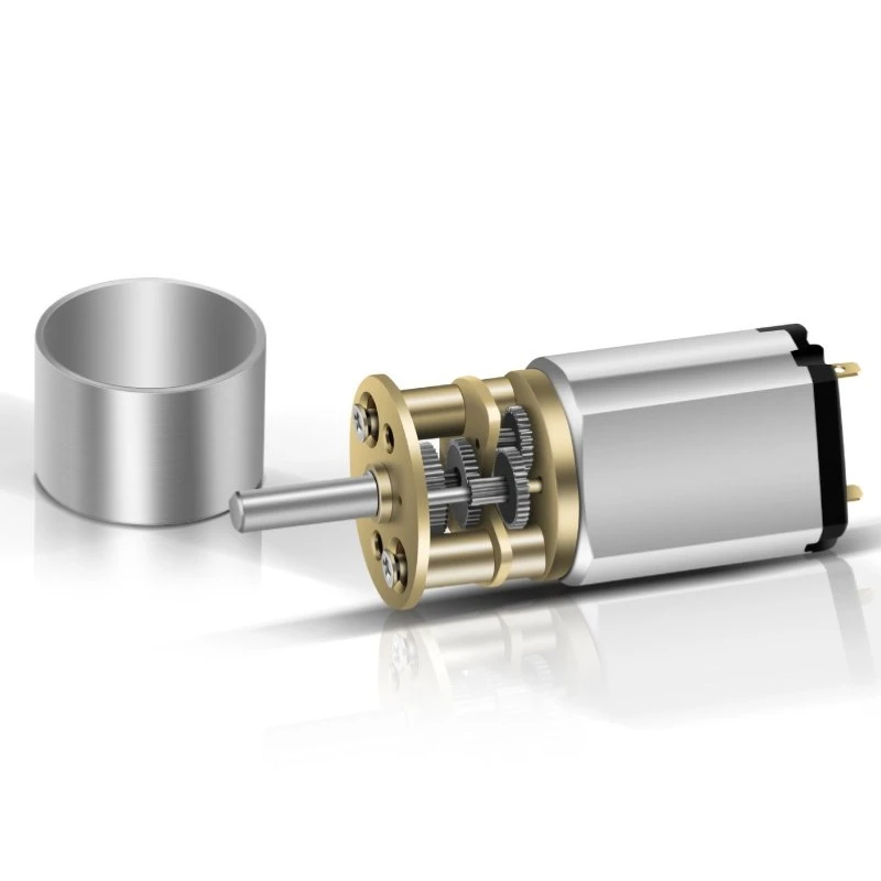
The Spur Gear Motor combines a DC motor with a multi-stage spur gearbox to provide a mature, efficient, and cost-effective drive solution for compact transmission mechanisms. Its simple gear structure supports flexible ratio, shaft, and mounting customization, making it suitable for smart home devices, commercial equipment, automotive actuators, smart landscaping systems, and industrial automation. It is a practical choice for projects that need a balance of output speed, torque, reliability, manufacturability, and cost.
The GM12 Series is a compact 12 mm-class DC spur gear motor platform developed for miniature mechanisms that require efficient speed reduction, controlled output, and cost-effective integration in limited space.
The GM13AM Series is a compact 13 mm-class DC spur gear motor designed for miniature mechanisms that require efficient speed reduction, stable low-speed output, and cost-effective transmission in a limited installation space.
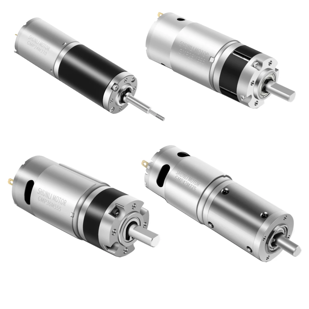
The Planetary Gear Motor uses a compact coaxial planetary gearbox to deliver higher torque density and stable transmission within limited installation space. Multiple planet gears share the load, making the structure suitable for applications that require compact size, reliable load handling, and frequent start-stop or reversing motion. It is widely used in robotics, medical equipment, industrial automation, automotive actuators, precision mechanisms, and other compact motion systems. Final selection should consider output speed, continuous and peak torque, duty cycle, backlash, current, and installation requirements.
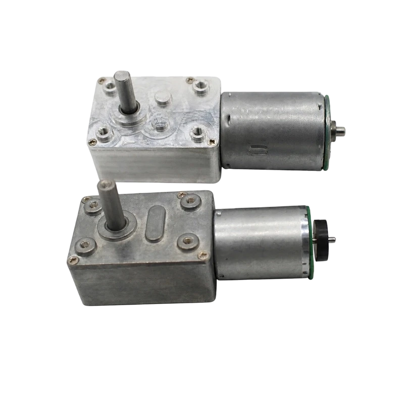
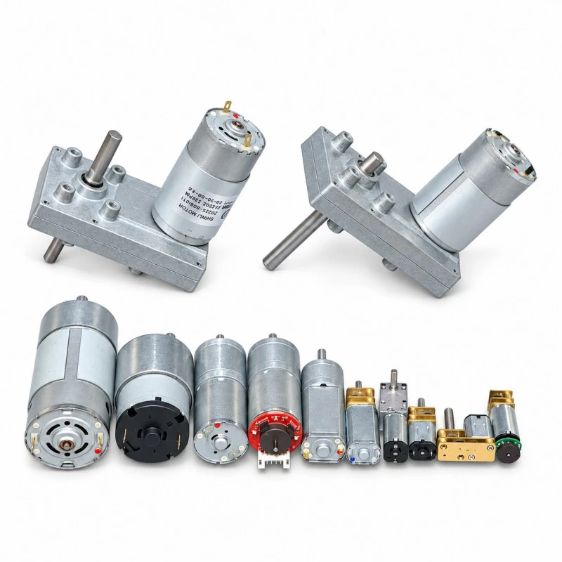
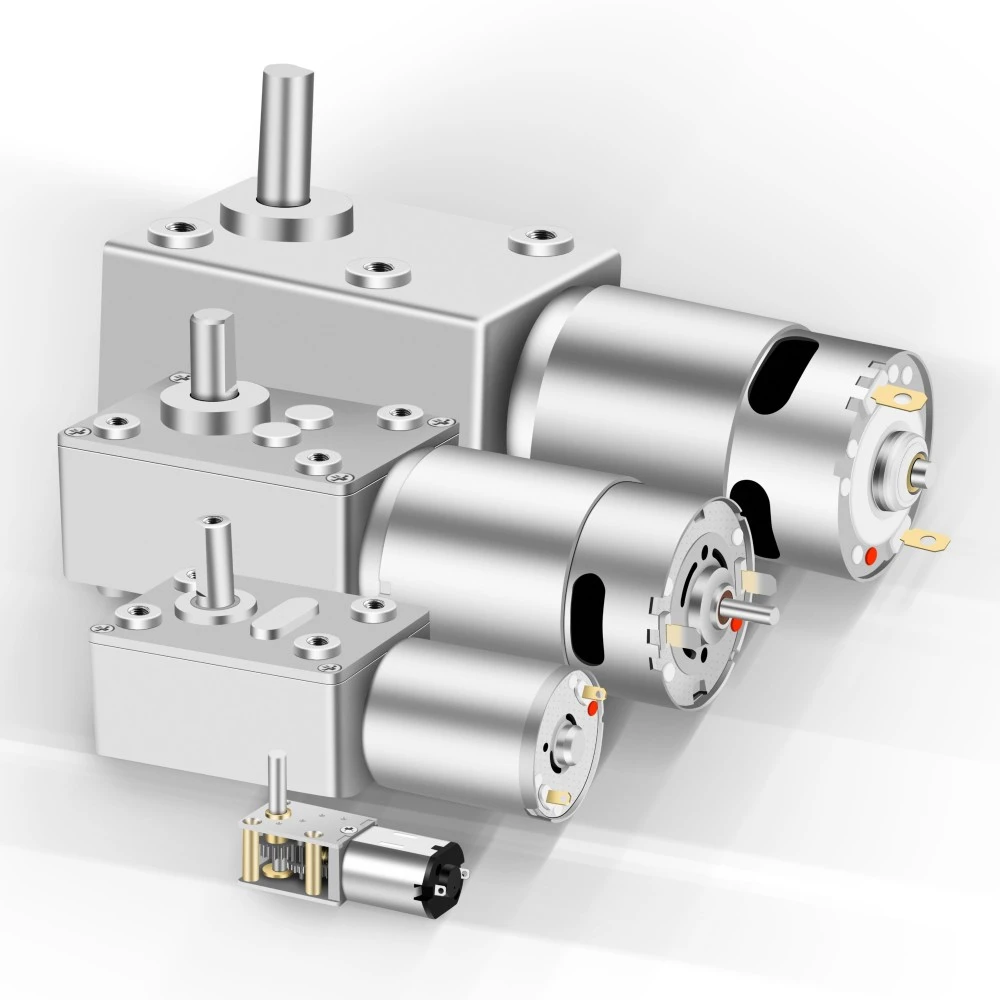
The DC Worm Gear Motor combines a DC motor with a worm gearbox to provide right-angle transmission, high reduction ratios, low-speed output, and strong load-driving capability in a compact structure. Its 90° output arrangement is well suited to valves, lifting and adjustment mechanisms, doors and windows, vending equipment, and other actuators where space layout or load-holding performance is important. Depending on the gear geometry and operating conditions, some worm gear designs may provide holding or self-locking characteristics, which should be verified for the actual application.
The GM16 Series is a compact 16 mm-class DC spur gear motor platform designed for miniature transmission systems that require efficient speed reduction, controlled low-speed output, cost-effective construction, and repeatable mass production.
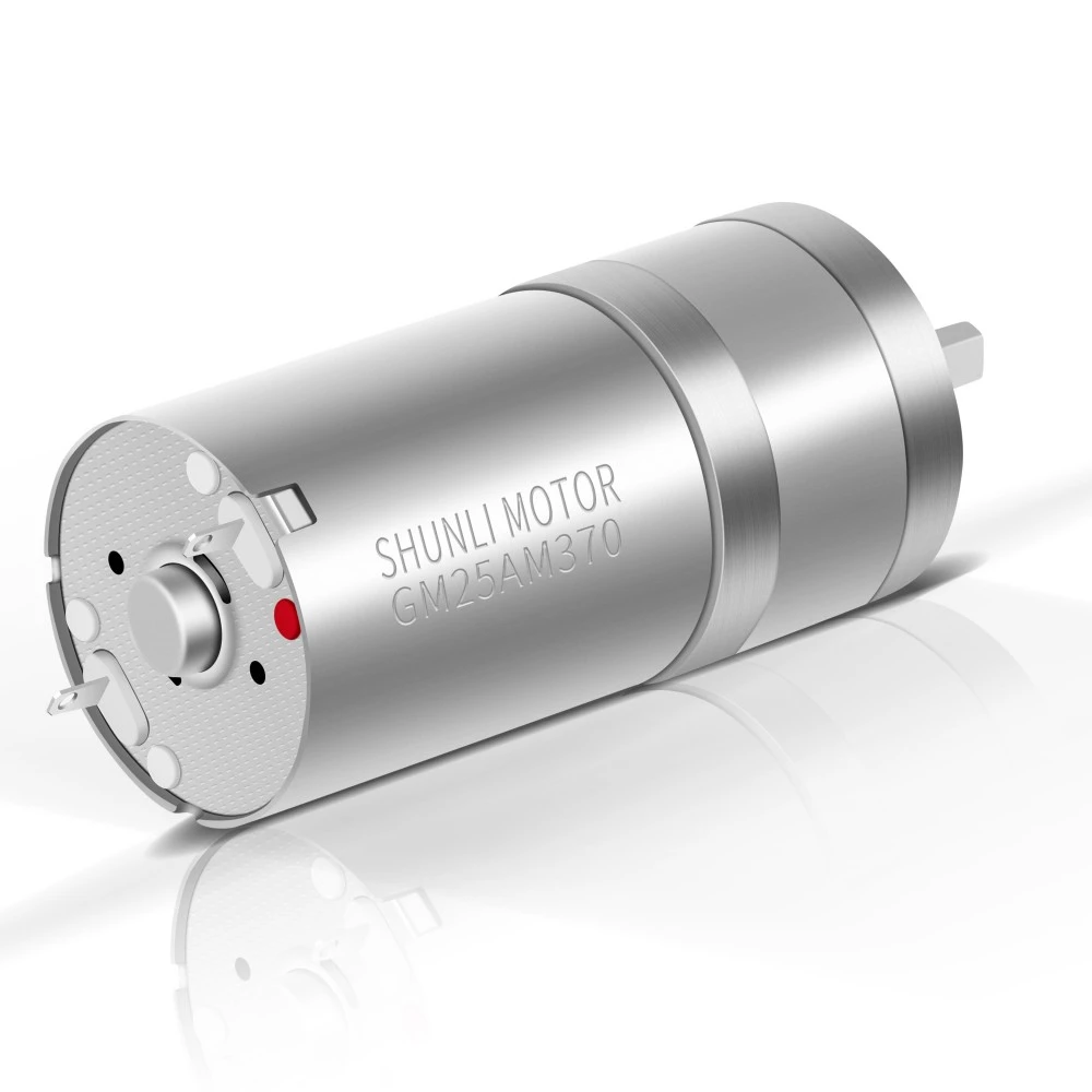
The GM25AM310/370 is a 25 mm-class DC spur gear motor platform combining a compact multi-stage gearbox with PMDC 310 or 370 motors. The supplied technical data covers gearbox options from 3 to 8 stages, multiple reduction ratios, and two reference gearmotor configurations: GM25AM310-217K at 3 VDC and GM25AM370-99K at 12 VDC.
The GM24 Series is a compact 24 mm-class DC spur gear motor platform developed for small transmission mechanisms that require efficient speed reduction, stable output, and cost-effective mass production.
Navigation
Navigation
Product Categories
Product Categories
Contact Us
Get in Touch
Get in Touch
Request a Quote


 Youtube
 Tiktok
 Linkedin
 Instagram
 Facebook
 WhatsApp
 WeChat